Connectors and Interfaces
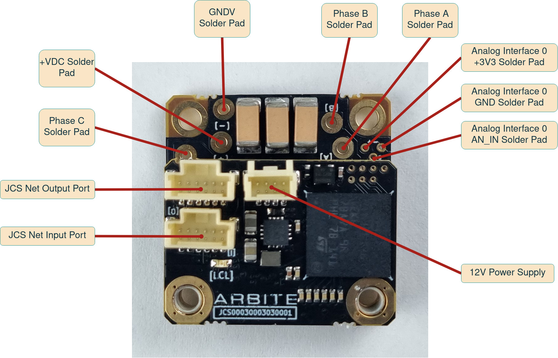
DC Bus Input
Input connector for DC bus power. Nominal 48V, but can operate anywhere in between limits defined in JCS Standard Voltages.
Connector
| Connector type | 1.3mm PCB solder through holes (Up to 16AWG) |
Pins Description
| Pin | Signal | Description |
|---|---|---|
| + | +VDC | DC bus power input |
| - | GNDV | DC bus power return |
WARNING:
No reverse polarity protection is implemented on the high power connectors.
WARNING:
Motor may act as a generator and energy may be produced at these pins. The source supplying these pins must account for this.
WARNING:
This connection is NOT hot pluggable. Ensure the system is powered down before removing or plugging in.
3 Phase Motor Interface
Connector
| Connector type | 1.3mm PCB solder through holes (Up to 16AWG) |
Pins Description
| Pin | Signal | Description |
|---|---|---|
| A | A | Motor phase A connection |
| B | B | Motor phase B connection |
| C | C | Motor phase C connection |
WARNING:
This connection is NOT hot pluggable. Ensure the system is powered down before removing or plugging in.
12V Supply Interface
Connector
| Connector type | Molex PicoClasp 4 Pins |
| Mating part number | 5019390400 |
Pins Description

| Pin | Signal | Description |
|---|---|---|
| 1 | +12V | +11V minimum, +13V maximum |
| 2 | +12V | |
| 3 | GND | |
| 4 | GND |
NOTE:
This connection is required. The device does not generate internal 12V from the DC Bus input.
WARNING:
This connection is NOT hot pluggable. Ensure the system is powered down before removing or plugging in.
JCS Network Interface
One network input connector and one network output connector. Interface is galvanically isolated. Power to the isolated side of the network is derived from the host device, eg a joint controller.
NOTE:
Differential and power pairs should be twisted: Twist wires connected to pins 1-2 together. Twist wires connected to pins 3-4 together. Twist wires connected to pins 5-6 together.
NOTE:
If this device is the last in a network chain the output must have the loop back connector installed.
WARNING:
This connection is NOT hot pluggable. Ensure the system is powered down before removing or plugging in.
Connector
| Connector type | Molex PicoClasp 6 Pins |
| Mating part number | 5013300600 |
Wiring Diagram

WARNING:
This connection is NOT hot pluggable. Ensure the system is powered down before removing or plugging in.
Analog Channel Interface
Specification
| Input | Single ended, ESD protected |
| Input voltage range | 0V - 3.3V |
| Resolution | 12 bits, 0.806mV / ADC count |
| Input filter | 1st order, -3db 30kHz |
NOTE:
This analog channel interface does NOT have an active buffer. Only connect low impedance sources.
Connector
| Connector type | 0.5mm PCB solder through holes |
Pins Description
| Pin | Signal | Description |
|---|---|---|
| + | +3V3A | 3.3V analog out |
| - | GNDA | Analog return |
| s | AN_IN | Analog signal in |
WARNING:
This connection is NOT hot pluggable. Ensure the system is powered down before removing or plugging in.