Connectors and Interfaces
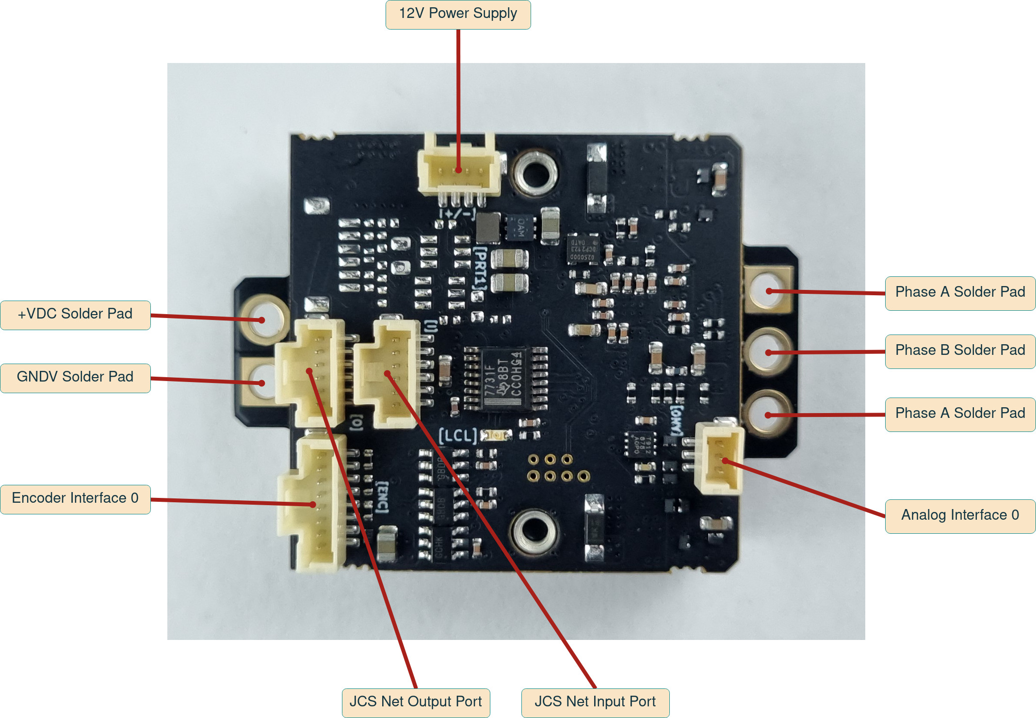
DC Bus Input
Input connector for DC bus power. Nominal 72V, but can operate anywhere in between limits defined in JCS Standard Voltages.
Connector
| Connector type | PCB solder pads, with M3 holes / AMASS XT30F |
Pins Description
| Pin | Signal | Description |
|---|---|---|
| 1 | +VDC | DC bus power input |
| 2 | GNDV | DC bus power return |
WARNING:
No reverse polarity protection is implemented on the high power connectors.
WARNING:
Motor may act as a generator and energy may be produced at these pins. The source supplying these pins must account for this.
NOTE:
Device has an 85V TVS diode across the power bus input.
WARNING:
This connection is NOT hot pluggable. Ensure the system is powered down before removing or plugging in.
3 Phase Motor Interface
Connector
| Connector type | PCB solder pads, with M3 holes |
Pins Description
| Pin | Signal | Description |
|---|---|---|
| 1 | A | Motor phase A connection |
| 2 | B | Motor phase B connection |
| 3 | C | Motor phase C connection |
WARNING:
This connection is NOT hot pluggable. Ensure the system is powered down before removing or plugging in.
12V Supply Interface
Connector
| Connector type | Molex PicoClasp 4 Pins |
| Mating part number | 5019390400 |
Pins Description

| Pin | Signal | Description |
|---|---|---|
| 1 | +12V | +11V minimum, +13V maximum |
| 2 | +12V | |
| 3 | GND | |
| 4 | GND |
NOTE:
This connection is required. The device does not generate internal 12V from the DC Bus input.
WARNING:
This connection is NOT hot pluggable. Ensure the system is powered down before removing or plugging in.
JCS Network Interface
One network input connector and one network output connector. Interface is galvanically isolated. Power to the isolated side of the network is derived from the host device, eg a joint controller.
NOTE:
Differential and power pairs should be twisted: Twist wires connected to pins 1-2 together. Twist wires connected to pins 3-4 together. Twist wires connected to pins 5-6 together.
NOTE:
If this device is the last in a network chain the output must have the loop back connector installed.
WARNING:
This connection is NOT hot pluggable. Ensure the system is powered down before removing or plugging in.
Connector
| Connector type | Molex PicoClasp 6 Pins |
| Mating part number | 5013300600 |
Wiring Diagram

WARNING:
This connection is NOT hot pluggable. Ensure the system is powered down before removing or plugging in.
Analog Channel Interface
Specification
| Input | Single ended, ESD protected |
| Input voltage range | 0V - 3.3V |
| Resolution | 12 bits, 0.806mV / ADC count |
| Input filter | 1st order, -3db 30kHz |
Connector
| Connector type | Molex PicoClasp 3 pins |
| Mating part number | 5013300300 |
Pins Description

| Pin | Signal | Description |
|---|---|---|
| 1 | +3V3 | 3.3V out |
| 2 | GND | Analog return |
| 3 | AN_IN | Analog signal in |
WARNING:
This connection is NOT hot pluggable. Ensure the system is powered down before removing or plugging in.
Encoder Interface
Encoder interface supports either differential or single-ended quadrature, SPI/SSI or UART based encoders.
Connector
| Connector type | Molex PicoClasp 8 pins |
| Mating part number | 5013300800 |
Pins Description

| Pin | Signal | Description |
|---|---|---|
| 1 | +5V | 5V out |
| 2 | GND | Ground |
| 3 | A+ / DTA+ / RX+ | Differential incremental encoder A+ input Single ended incremental encoder A input Differential SPI / SSI data+ input Single ended SPI / SSI data input Differential UART RX+ input Single ended UART RX data input |
| 4 | A- / DTA- / RX- | Differential incremental encoder A- input Differential SPI / SSI data- input Differential UART RX- input Leave floating for single ended |
| 5 | B+ / CLK+ / TX+ | Differential incremental encoder B+ input Single ended incremental encoder B input Differential SPI / SSI clock+ output Single ended SPI / SSI clock output Differential UART TX+ output Single ended UART TX data output |
| 6 | B- / CLK- / TX- | Differential incremental encoder B- input Differential SPI / SSI clock- output Differential UART TX- output Leave floating for single ended |
| 7 | IDX+ / CS+ | Differential incremental encoder index+ input Single ended incremental encoder index input Differential SPI / SSI chip_select+ output Single ended SPI / SSI chip_select output |
| 8 | IDX- / CS- | Differential incremental encoder index- input Differential SPI / SSI chip_select- output Leave floating for single ended |
INFO:
Encoder connection is 1-1. For example DTA+ on the encoder end connects to DTA+ on the controller end.
NOTE:
Differential and power pairs should be twisted: Twist wires connected to pins 1-2 together. Twist wires connected to pins 3-4 together. Twist wires connected to pins 5-6 together. Twist wires connected to pins 7-8 together.
WARNING:
This connection is NOT hot pluggable. Ensure the system is powered down before removing or plugging in.