Installation
Mounting features
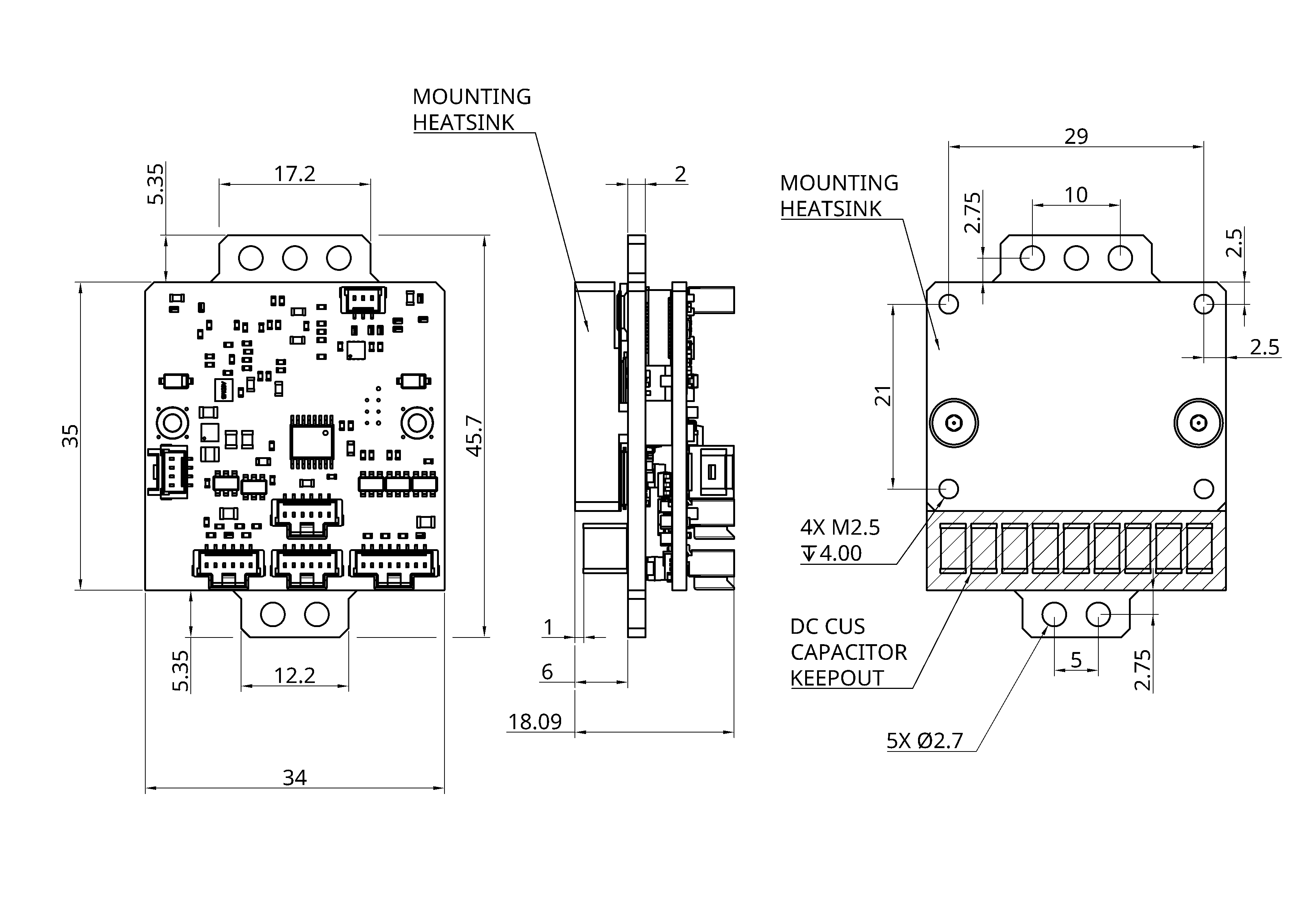
CAD model
Mounting the device
dev_motor_controller_7250 features an integrated heatsink that is thermally connected, but electrically isolated from the power MOSFETs. The heatsink has 4xM2.5 (0.45mm thread pitch) threaded holes with a maximum depth of 4mm.
WARNING:
DO NOT exceed the maximum threaded hole depth of 4mm. Damage to the device may occur.
Prior to mounting the device ensure the heatsink surface is clean and free of debris. The heatsink surface may be cleaned with an appropriate solvent, e.g. isopropyl alcohol (IPA).
Use a thermal grease (preferred) or pad to thermally interface to the mating surface.
When screwing to the mating surface take care to ensure the M2.5 threads do not get stripped. A good approach when installing the screws is to wind the screw backwards until you feel it 'click' into the thread. Then proceed to tighten the screw.
Torque the screws to 0.4Nm.
Thermal Considerations
dev_motor_controller_7250 is built on 6 layer, 3oz PCB and features an integrated heatsink. The heatsink mating surface is machined and electrically isolated.
Peak current is a fixed property of the device design, whereas continuous current capability is dependent on the devices thermal integration into the surrounding system. The best continuous current performance is obtained when dev_motor_controller_7250 is mounted to a surface of fixed temperate, e.g. an actively cooled plate.
Device wiring
dev_motor_controller_7250 is designed to have the power wiring and motor phase wiring soldered to the power stage of the device. Note: The power connector hole size and spacing is also suitable for a 2 pin AMASS XT30F.
Consider the following when soldering the wires into place:
- Ensure no voltage is present on the device or wires!
- Make sure to pre-tin the wires.
- Use flux on the solder pads. The flux residue can be cleaned with an appropriate solvent, eg isopropyl alcohol (IPA).
- Consider the thermal capacity of the PCB. Make sure to use a soldering iron powerful enough to get heat into the wiring and connectors quickly enough as to avoid damage to the device.
- Ensure enough wire is used the the device can be serviced.