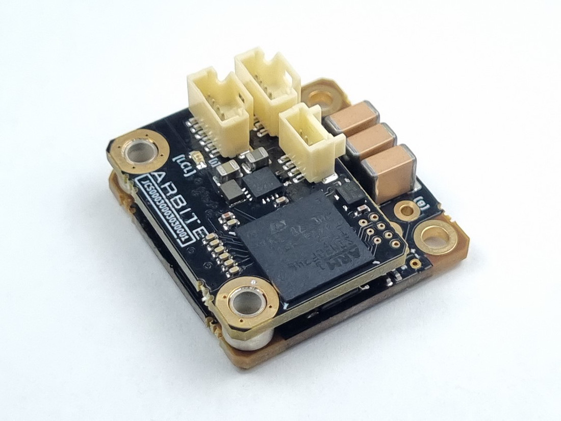
Specifications

General Hardware Specifications
| Mass | 11g |
| Dimensions | 28mm x 28mm x 12.5mm |
| Analog input | 1 x single ended (0 - 3.3V). Solder-able connection on power board |
| Encoder input | Onboard encoder, no external encoder supported |
| Position resolution | 14bits (16384 counts / rev) |
| Temperature sensing | 1 temperature sensor on power board |
| Safety protections | Over/under-temperature Over-current Over/under-voltage Loss of host Position sense fault Configurable fault on analog input |
| Supports JCS processes | Yes |
| Supports JCS device rate | Yes |
| JCS device rate frequency | 10kHz |
Electrical Specifications
| DC bus maximum voltage | +48V continuous, +52V peak (100mS), E-Stop at +60V |
| DC bus minimum voltage | +20V continuous, E-Stop at +18V |
| DC bus capacitance | 30uF |
| Phase current sensing | 2 phases measured, in-line shunt based, 3rd phase computed from measured quantities |
| Maximum phase current | 5A continuous (thermally limited), 8A peak Active current limiting based on device temperature |
| Phase voltage sensing | All 3 phases |
| PWM frequency | 30kHz |
| Current control loop frequency | 30kHz |
| 12V supply maximum voltage | 13V |
| 12V supply minimum voltage | 11V |
| 12V supply nominal current draw | 120mA (Device running) Actual current draw can vary up to this amount as the motor current varies |
| 12V supply capacitance | 22uF |
| Joint controller 5V interface burden | 3mA (15mW) Device draws this current from the joint controller 5V supply to power the isolated communications interface |
NOTE:
The device uses 100V rated ceramic capacitors. Note that DC bias effects will be present and the effective bus capacitance will go down as the bus voltage goes up. Add external capacitance close to the device power inputs if the application demands it.