Installation
Mounting features
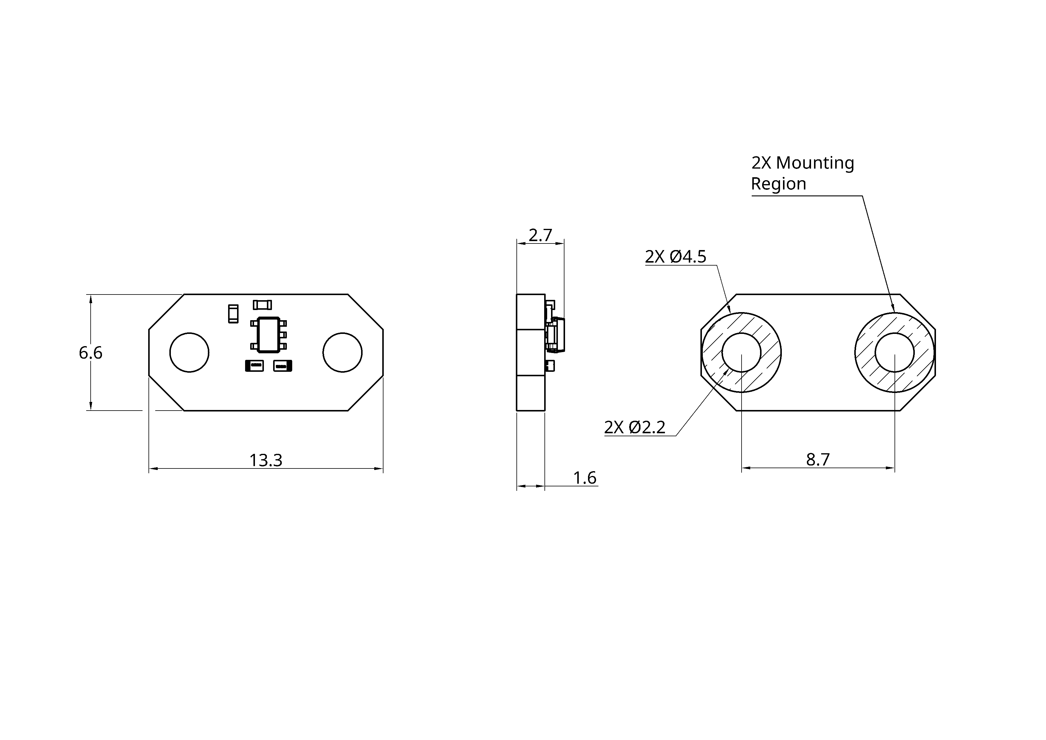
CAD model
Device wiring - soldered connections
The temperature sensor is designed to have the power and sensor wiring soldered directly to the PCB, to ensure the small size of the device. It is advised to crimp a connector to the free wire end (for example a JCS analog interface mating connector).
Consider the following when soldering the wires into place:
- Ensure no voltage is present on the device or wires!
- Make sure to pre-tin the wires.
- Use flux on the solder pads. The flux residue can be cleaned with an appropriate solvent, eg isopropyl alcohol (IPA).
- Ensure enough wire is used the the device can be serviced.
Sensor Mounting Considerations
The bottom side of the sensor PCB has the solder mask layer omitted to expose the copper connection to the sensor ground. This is to improve the thermal performance of the sensor.
The exposed copped is electrically connected to the sensor ground and must be electrically isolated from the mating surface. Use an electrically isolating thermal pad between the sensor PCB and the mating surface.
Mounting points are provided on the PCB in the form of 2x M2 screw holes. The mounting points surrounding copper is not electrically connected to the sensor ground.